Temperature
The temperature difference between the chilled/condenser water supply and return temperature (°C) is used to compute the net cooling load delivered to the building, or amount of energy consumed by AHUs/FCUs (air handling units/ fan coil units). As an illustration, for a chilled water plant operating with a chilled water supply and return temperature difference of 5°C, a seemingly acceptable error of ±0.5°C can in fact lead to a 20% error in the final computation of the system cooling load.
In addition, many energy audits conducted on existing buildings have shown that a large number of existing chiller plants experience a low delta T syndrome (i.e. temperature difference of about 2 °C to 3 °C), especially when they operate at part load conditions. In such circumstances, the error in the cooling load computation is even greater.
A maximum uncertainty of ± 0.05°C end-to-end for each temperature measurement is thus required, to allow for optimisation of the plant operation. Since the lifetime of a typical chiller plant is 15 to 20 years, it is important to install highly accurate temperature sensors for long-term accurate trending of the operational efficiency of the plant.
The end-to-end uncertainty encompasses the entire chain of the temperature measurement process, i.e. the temperature sensor, transmitter, wiring, data acquisition system, etc. Typical sources that introduce errors in the measurement chain include:
-
Thermowell type
Temperature sensors installed in thermowells are not in direct contact with the water (ie Closed-end thermowell) and this might have an impact on the accuracy. In addition, the conductive thermal compound within the thermowells tends to dry out over time, which will affect thermal conductivity.
-
Location of temperature sensors
Care should be taken if sensors for the chilled water supply are installed in locations exposed to direct sunlight. The metal parts of the sensor could easily reach 50°C due to direct solar radiation.
Installation of temperature sensors near pipe joints from 2 different sources might cause unstable measurements due to mixing of water temperatures.
-
Use of transmitters
Some systems use transmitters to convert the sensor resistance from ohms to 4~20 milliamps (mA) DC signal to allow for transmission over a long distance. There is a tendency for the transmitters to drift over time, and be affected by ambient temperature fluctuations.
-
A/D conversion in Data Logger
An additional source of error is introduced when an A/D convertor is used to convert the analogue signal of ohms or mA from the sensor or transmitter into digital signals for processing by a computer.
-
Sensor(s) affected by electromagnetic field
Most of the sensors are installed in environments with high Electromagnetic field, where a typical chiller plant room houses the chillers, pumps, fans, inverters, and sometimes, even high voltage transformers. The interference from the electromagnetic field due to these equipment may affect wireless or even improperly-shielded wired communication.
Most chillers in the market are factory-tested to rigorous standards in accordance to ANSI/AHRI Standard 550/590 which specifies an allowable tolerance of 5% for capacity, efficiency and heat balance. Separate meters are used during the factory test rather than the built-in sensors in order to achieve the required uncertainty level. Other measurement standards such as ASHRAE guideline 14 and ASHRAE Guideline 22 have also stated the use of independent sensors rather than the chiller’s built-in sensors.
The majority of BAS in the market address issues of comfort, safety, convenience, manpower savings, etc. However, they do not specifically target accurate measurements to attain long-term chiller plant efficiency within ±5% at the moment. Moreover, the existing BAS may not have the excess capacity to add I/O points for measurements and the capability to use the meter’s data output protocol. In hot and humid climates such as Singapore, the majority of commercial buildings have cooling needs year-round, and the cooling system of a building can sometimes account for 30% to 50% of the total energy usage. Hence, it is necessary to install accurate M&V instrumentation to ensure that chiller plants operate efficiently over its life cycle.
Temperature sensors are not required for individual chillers. For GM NRB V4.1 and ENRB V3.0, temperature sensors are to be provided for chilled water and condenser water loop at the main headers, i.e. two (2) for measuring the supply and return temperature at the chilled water header and two (2) at condenser water header, a total of four (4) temperature sensors.
Although these temperature sensors are more expensive than standard BAS sensors, each calibrated sensor can be procured at about S$500.
Highly accurate M&V instrumentation was introduced in public sector retrofit projects through the Guaranteed Energy Savings Performance (GESP) programme about 5 years ago. To date, the public sector has awarded over a dozen contracts with stringent M&V requirements. Many vendors are involved, and more of such contracts are in the pipeline. The M&V standard in public sector retrofits is set even higher at ±0.03°C endto-end measurement uncertainty.
A list of accredited ESCOs (Energy Services Companies) is available on the National Environment Agency website, which features MNCs and local SMEs. Some of the ESCOs maintain their own calibration labs; and some also offer performance guarantee through energy performance contracts with financing.
Since 2013, BCA has also started registering competent persons familiar with the M&V standards and practices under the BCA Energy Auditors Scheme. The list of Energy
Auditors registered with BCA can be found in the BCA website. The BCA Academy also conducts a regular course on Measurement and Verification of Central Chilled Water Plant Performance, more information is available on the BCAA website.
The Green Mark standard is performance-based and technology-neutral. BCA accepts any measurement system that can provide a long term end-to-end temperature measurement uncertainty of ± 0.05°C. In a typical chiller plant, temperature ranges from 0°C to 40°C, 10KΩ thermistors have been shown to offers good sensitivity to changes in temperature; whereas a relative change in resistance (temperature coefficient of resistance) in PT100 varies only slightly for the above temperature range.
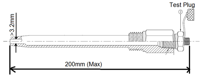
BCA’s test probe used for site verification is 228mm long and 3.2mm in diameter. For proper insertion, the thermowell should have an open tip slightly larger than 3.2mm diameter, and the length of the assembly including isolation valve (if any) andthe test plug should not exceed 200mm length. This would ensure that the test probe is in direct contact with the water.
BCA also accepts spare test plugs without thermowell as long as the test probe is able to come in direct contact with the water especially for pipes with larger diameter.
The verification of chilled water plant instrument using the heat balance –substantiating test shall be in accordance to AHRI 550/590. The heat balance shall be conducted over the entire normal operating hours with more than 80% of the computed heat balance within ±5% over the audit period (1 week).
The computation formula is as follows:
For open drive chillers, the Winput shall take into account the motor efficiency provided by the manufacturer. An example is provided as follows:
Input power (measured) = 100kW
Motor rated efficiency (η) = 90%
Adjusted Winput = 100kW x90%
= 90kW
In the event where hydraulic losses of pumps constitute a substantial heat gain, these losses have to be properly accounted for. The value shall be determined from pump efficiency values provided by the manufacturer. An example is as follows:
Motor input power (measured) = 30kW (A)
Motor rated efficiency (η) = 90% (B)
Pump rated efficiency (η) = 80% (C)
Hydraulic losses = (A) x (B) x (100%- (C) )
= 30kW x90% x(100%-80%)
= 5.4kW
Adjusted Winput = kWi(chillers) + 5.4kW
Yearly calibration is not required if the heat balance meet the requirement of within ±5% for 80% of normal operating hours. However, if the heat balance fails, it is an indication that some of the sensors have drifted. The project team has to investigate the possible cause, and may need to send the sensors for calibration.


